

Introduction: The Load, the Heat, and the Leap
Define the system, and the story gets clear. In a busy plaza at dusk, ten bays push high current at once; the queue inches forward, and uptime is king. A liquid cooling module steadies the scene, holding temperatures where electronics last longer and users move on faster. Peak fast-charge sessions can push hundreds of amps at up to a kilovolt, which drives heat into power stages and busbars. When heat stays trapped, failure rates climb and service teams scramble—often at the least convenient hour. So the core question stands: how do we move from “it runs” to “it runs cool, safe, and repeatable” without ballooning costs?
(Look, it’s simpler than you think.) The answer starts with how we handle energy density and sustain thermal margins over time. Are we treating heat as a nuisance or as a design input with the same weight as voltage and current? Let us set a baseline, then compare where newer designs change the outcome. Onward to the real friction points.
Why frame it this way?
Hidden Fault Lines in Traditional Fast Chargers
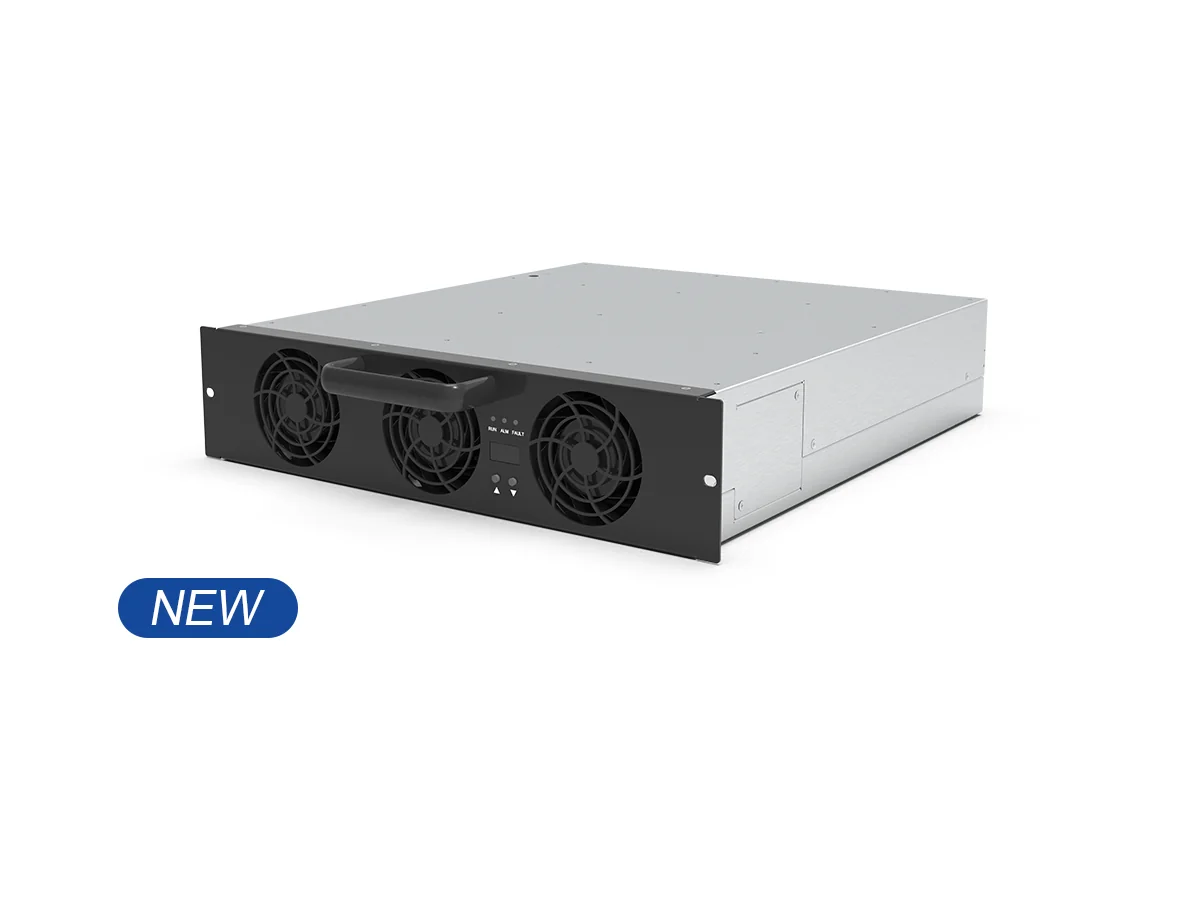
Consider the 1000v EV Dc charger module as the anchor, then contrast it with air-cooled habits. Legacy cabinets often rely on big fans, long ducts, and wide clearances. That creates uneven airflow and hotspots around DC link capacitors and power converters. When thermal gradients stack up across busbars and IGBT or SiC MOSFETs, the system derates early. Fans ramp, noise rises, and yet sensitive parts still see higher junction temps. Over time, dust and humidity reduce effective airflow; filters clog, bearings wear, and thermal runaway risks do not always announce themselves. It is not just heat; it is heat with poor direction.

Look, it’s simpler than you think: the flaw is mismatch. High current paths sit far from optimal cooling paths, and that gap widens under peak load. Edge cases—back-to-back sessions, summer heatwaves, or cramped urban sites—turn minor inefficiencies into service calls. Maintenance windows stretch, and energy use for fans eats into OPEX. Even clever control loops cannot fix physics if the coolant never reaches the hot silicon or inductors at the right rate. The silent pain points are uneven temperature maps, shortened MTBF for gate drivers, and time lost swapping parts that aged fast—funny how that works, right?
Where do legacy designs stumble?
Principles That Change the Curve
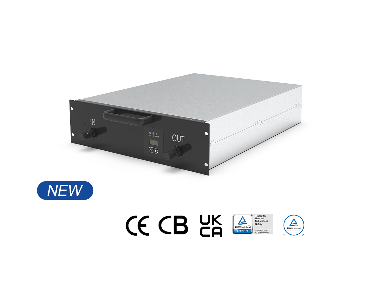
Shift the lens to new technology principles. Liquid paths put cooling where heat is born—at the module, not the room. A well-designed manifold targets high heat flux zones near rectifiers and chokes, then returns fluid with minimal pressure loss. The result: tighter delta-T across phases, steadier junction temperatures, and less derating during rush hours. A modern liquid-cooled charging module couples thermal control with compact packaging, so cable runs shrink and parasitics fall. That helps switching devices and reduces EMI stress. Add sensors for inlet and outlet, and the system adapts in real time (not guesses). Service teams read clear data, not guesswork.
Compare this with airflow strategies. Air must move around corners and past wiring looms; liquid goes straight to source. With fewer moving parts, noise drops and filters vanish. Field swaps become modular: hose quick-connects, standardized seals, and known coolant chemistry. For operators, the gains stack: higher uptime, flatter derating curves, and a calmer thermal envelope for control boards and communication modules—even at edge computing nodes on site. And yes, that steadiness matters—because every degree you do not fight today is a day you do not schedule emergency maintenance.
What’s Next
Forward-looking sites will mix predictive control with liquid circuits. Think simple models that map coolant flow to real heat loads per gun, plus scheduled flushes that take minutes, not hours. Case in point: when coolant circuits stabilize a cabinet’s hottest zone, cable temperature drops, so users experience consistent charge rates from session one to session ten. Operators then measure wins in tangible terms: fewer derates, longer life for contactors, and quieter stations that fit dense urban zoning. Advisory close: choose wisely using three checks. First, verify heat density per kilowatt handled at the device face, not the cabinet door. Second, check derating thresholds versus ambient—in particular, hold power at 40–50°C without fan hysteresis. Third, audit service design: tool-free module swaps, sealed connectors, and coolant monitoring that flags leaks before downtime—because surprises are not a maintenance strategy.
Summed up, the comparative insight is clear. Air can cool a room; liquid cools the work. When the module aligns coolant paths with real heat sources, the rest of the system breathes easy—literally and financially. Keep the focus on thermal maps, component life, and the steady rhythm of field service. Then the numbers follow. For further technical reading and reference designs, see winline technology.